|
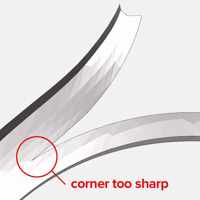
Sharp Edges
A common cause of investment wash is the CAD model containing sharp
edges, points or corners. Edges, points and corners should all be curved with a radius of
at least 0.125 mm (also known as rounding, filleting or edge softening).
Popular design software such as Matrix has plugins and functions to perform this task.
The most common sources of sharp edges are components with edges that
meet to a point and straight, sharp angles (such as split shanks or lettering).
|
|
Holes
Another cause of investment wash is when models contain aspects such as lettering, stone holes,
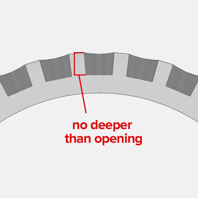
fine gaps or spaces that have a depth that is greater than the width of the opening. The
depth of the void should not exceed the width of the opening of the void. The
maximum depth of a hole should not exceed 0.30 mm
If the design requires holes, then a small pilot divot is better, allowing for the entire hole to
be drilled out later.
Adequate spacing between parts or components that are not meant to be touching is important.
Small gaps or voids can be sources of investment wash or poor formation.
|
|
Gaps and Voids
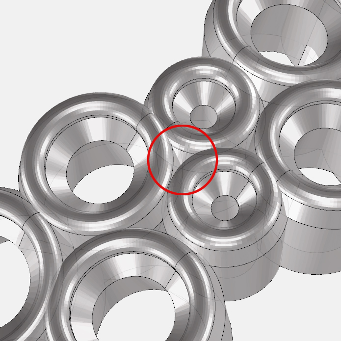
Always maintain a gap of at least 0.20 mm between components such as claws, setting
posts and walls. If this is not possible, fill the gaps and drill them out
later.
Ensure that any holes are greater than 0.20 mm in diameter and do not have a depth larger than the
diameter or opening of the hole.
If the design requires a pilot hole, then a small pilot divot is better, allowing for the entire
hole to be drilled out later.
|
|
Material Thickness
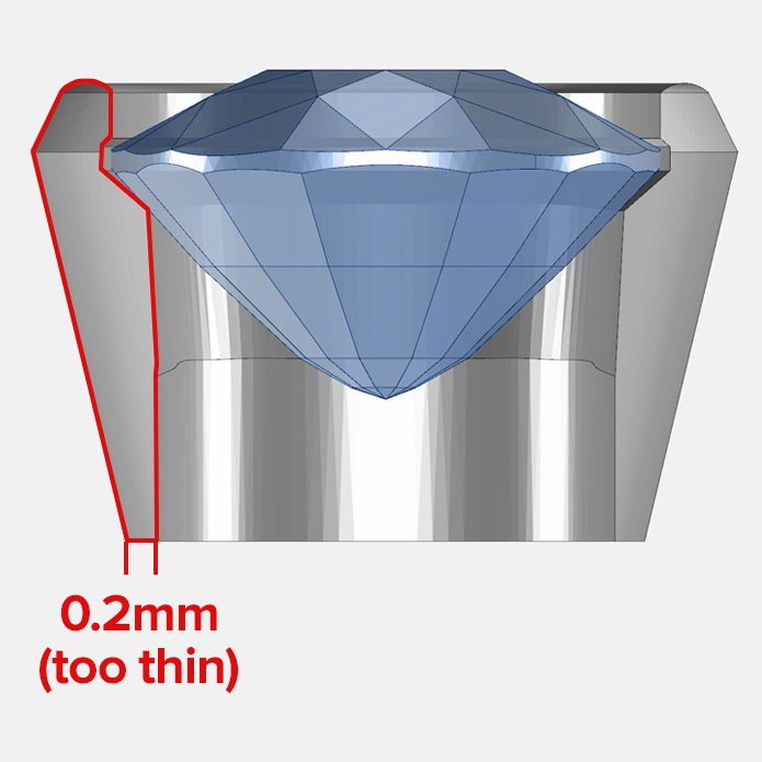
The wall and component thickness should be considered when creating
designs.
Cast material that is too thin may cause shrinkage, porosity, distortion, or breakages.
Factors such as the surface area and complexity of the design may require greater design
thicknesses.
The minimum design thickness should be at least 0.40 mm and
broad or flat areas should be at least 0.50 mm thick.
If the final piece is required to be moulded for multiple copies, then should be at least
0.90 mm thick.
|
|
Text and Lettering Design
CAD designs often include text, hallmarks, logos and stamps and are usually recessed into a
section of the design. While these designs look great and can be useful (particularly for showing a
maker’s mark or caratage) stylised fonts and impressions are not always conducive to successful
investment and casting. If the design includes these aspects, consider using square angles
or simple fonts such as Sans Serif. Avoid curved designs that taper to a fine point.
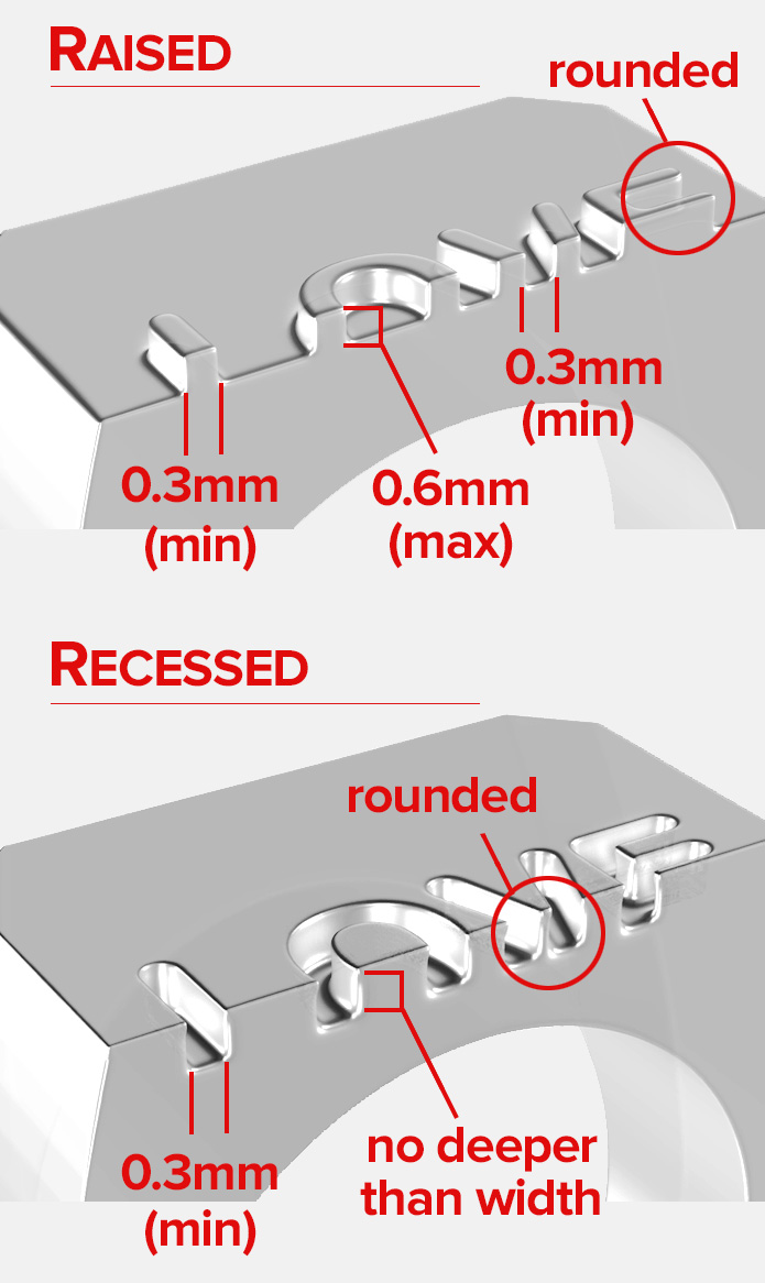
Raised text: designs must have a minimum width and spacing between letters of at
least of 0.30 mm. Raised text should only have a maximum height of 0.50 mm.
Recessed text: designs must have a minimum width and spacing between letters of at
least of 0.30 mm.
Recessed designs should be recessed to a maximum of 0.30 mm deep and no deeper than the width of
the opening.
If possible, draft or taper by 5-10 degrees so that the bottom of the impression is
narrower than the opening and avoid sharp corners ensuring that edges and corners are
rounded to at least 0.125 mm.
If a complex or highly stylised design is required, laser engraving may more suitable.
|
|
Naked Edges and Non-Watertight Models
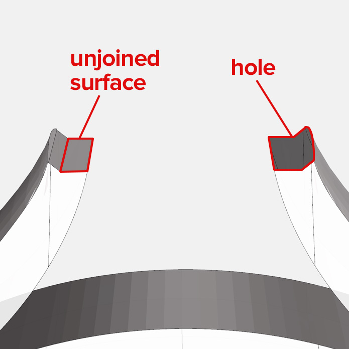
Naked edges are open edges which are not connected to any
neighbouring edges, producing a model that is not “watertight”. Non-watertight models can cause
print issues.
Naked edges might not be visible to naked eye and
may only show up when cleaning up.
Ensure to utilise the analysis and check functions in your CAD design
program to determine if your model is "watertight" and free of any naked edges.
Curved surfaces are a typical source of naked edges, particularly
with text designs on 3D files. Most text fonts are designed with graphic design in mind, not 3D
printing.
|
|
Unsupported Components and Protrusions
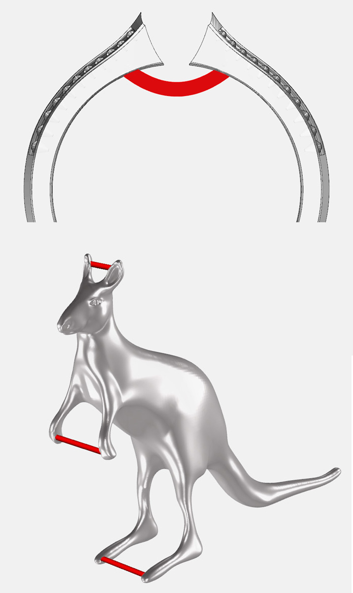
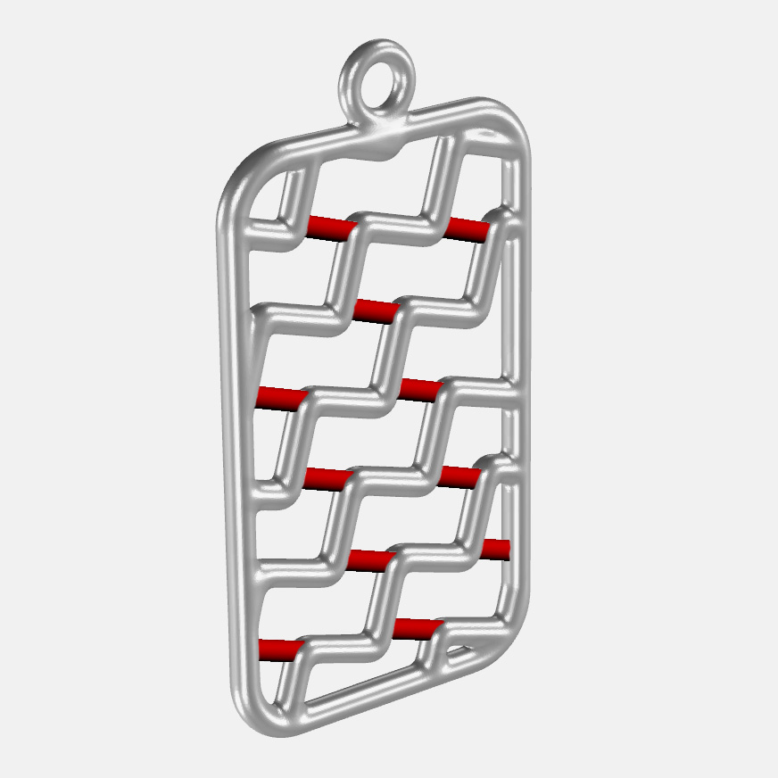
Designs that contain aspects that protrude or are poorly supported
can break off during the casting process, particularly at the wax handling (cleaning, treeing, etc)
and investment stage or they can twist and warp at the casting stage.
Please ensure that protruding and thin parts are thick enough to support themselves or
contain additional supporting sprues or strips to minimise the risk of breakage. The thickness
required is specific to the design.
Alternatively, a supporting or bridging sprue of at least
0.80 mm in diameter can be inserted on the drawing to add support.
This also applies to components that may have large gaps and openings
or unsupported protrusions (i.e. shanks that have an open gap to place the setting in, or claw
settings that may require a supporting halo sprue).
|
|
Multiple Parts and Components
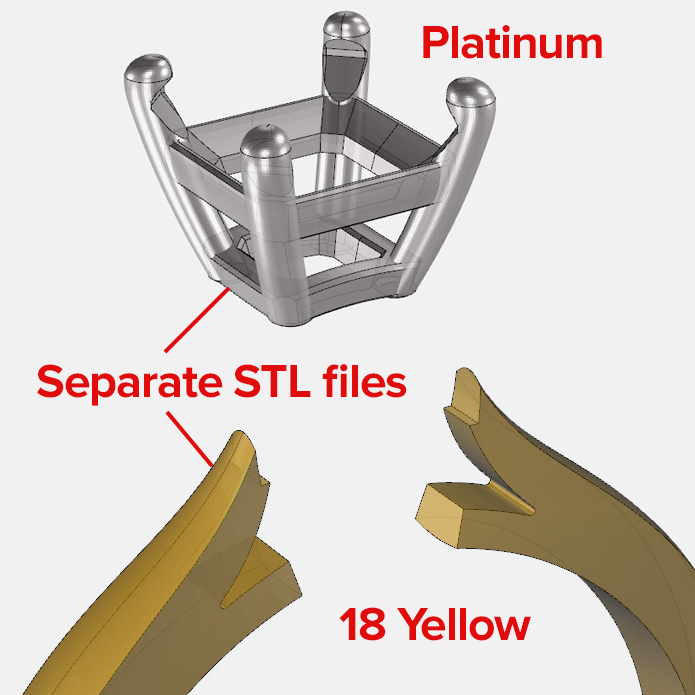
Designs with multiple parts or components (i.e. setting and shank)
need to be exported as separate STL files, especially for multiple components that are cast in
different alloys.
Designs with multiple parts or components that are to be cast in the same alloy need to be
connected via a sprue so they can be cast as one continuous piece.
Some designs can be printed and cast as one piece, but quality and
feasibility are not guaranteed. Best practice is to export multiple components into separate STL
files.
Multiple files may also allow for faster and tidier cleanup
of difficult to reach areas.
|
|
Finishing and Shrinkage
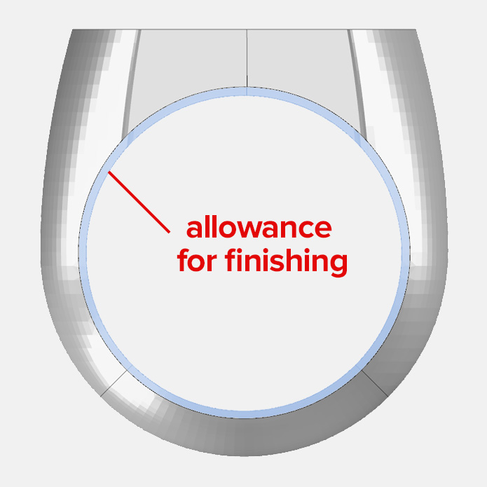
Castings are typically supplied in a semi-raw form with further
finishing required.
Finishing can remove up to 0.10 - 0.20 mm of the surface material, so this needs to
be factored into the design.
Shrinkage may also occur over the various stages of printing and
casting.
Allow for at least 1% shrinkage in gold and silver alloys and
2% for platinum alloys.
This is especially true for components where accurate dimensions are
required (e.g. stone setting spaces and finger holes in shanks).
|
 |
Identifying Marks
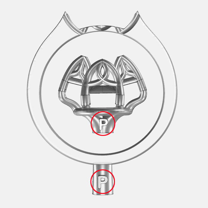
Multiple pieces with similar designs can be difficult to tell the difference between. Examples
include; multiple settings with slightly different stone sizes, rings/shanks with slightly
different finger sizes.
Please include an identifying mark to each piece. This can be a finger size on the inside of a
shank or a spure added to a setting that includes a number or another unique marking.
|
|
Designs That Restrict Metal Flow
Models that have design aspects with varying thicknessess and angles can restrict metal flow
during the metal injection process.
Main sprues are generally attached to the thickest part of the model to allow optimal metal
flow.
Design aspects that are thinner or encourage a longer or more complex metal flow path may
require additional feeder sprues to reduce the metal flow path length.
This can reduce the likelihood of components not forming properly or metal solidifying before it
can successfully fill all the required spaces.
|
